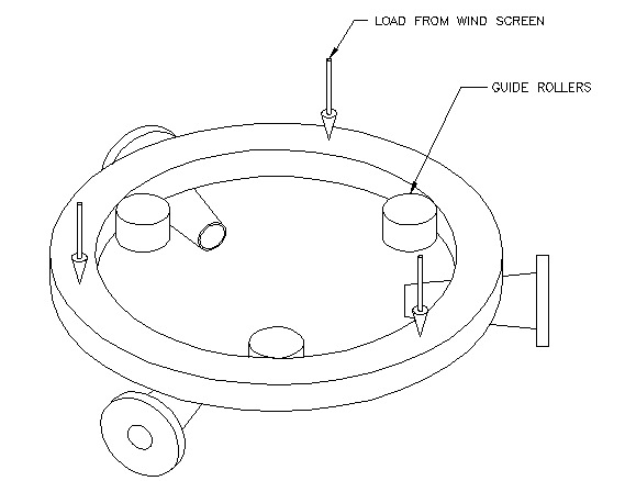
The wind baffle assembly weighs 11,000 lbs and stands on 3 rollers which are driven to rotate the assembly. The structure needs additional guidance because as it rotates it tries to walk over the lip of its drive rollers. The concept is to design a bracket to attach to the motor assembly which will roll against the ID of the wind screen support disk and prevent it from translating its axis with respect to the design azimuthal rotation axis.
I will check to see if the rollers as designed can withstand the design criterion. The design criterion is that the rollers should be able to resist the entire friction force necessary to slide the wind screen on its drive rollers. I will assume a coefficient of friction of 1.0, very clean steel on steel in line or edge contact. This sliding force is simply the weight x m, and a single roller needs to be able to resist it.
F = m (11,000 lbs) = 11,000 lbs.
The design proposed uses a McGill #CYR-2 3/4 with a 3/4" bore. The shaft is a McMaster Carr stainless steel dowel pin. I will use a yield strength for it of 35 ksi.
I did not have a McGill catalog, but upon comparing equivalent Torrington bearings in cam followers, I saw no cam follower with a limit load rating of under 14,000 lbs, so the rollers are OK.
Checking the shaft, it is in double shear, so the shear stress is:
![]()
By maximum shear stress theory, the yield strength in shear is half the tensile yield strength.
![]()
The factor of safety calculated from the above numbers is:
Given the conservative nature of this calculation, I would say that there is an acceptable margin of safety in the shaft.
The remaining calculations are on the bracket and bolt pattern holding the cam follower in place
The first calculation is a check on bearing stress in the holes of the bracket. The projected area of the holes is .75" X .406".
Calculating the required weld between the cam follower support plates and back plate.
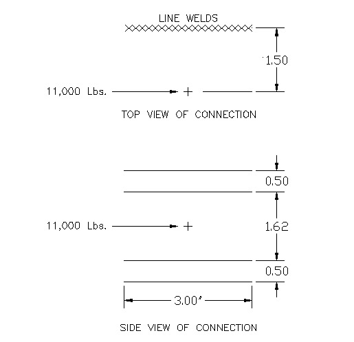
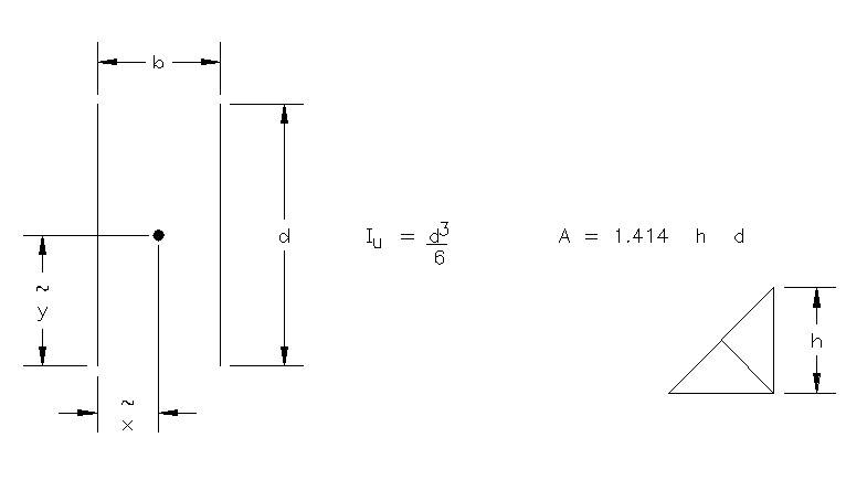
This is a weld group in bending and primary shear.
From Shigley, Mechanical Engineering Design, the bending:
The welds on the bottom bracket are double fillets, top is fillet and butt.
(I am neglecting the contribution from the butt weld. Its penetration will be < 3/32".)
As long as the fillet welds are larger than .03", the welds should be safe. They are specified to be .19", so the welds are fine in bending. Primary Shear:
Checking torsional shear stress in minimum cross-section of bracket:
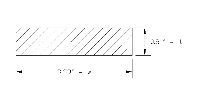
This torsional shear stress looks high. The bracket may need to be thicker.
The total thickness of the plate needs to be about 1.00". Cutting it below this may be risky. There is no reason not to thicken it.
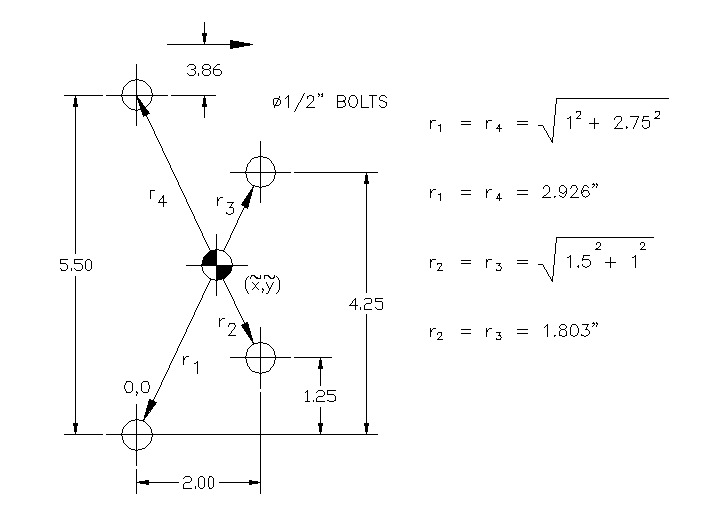
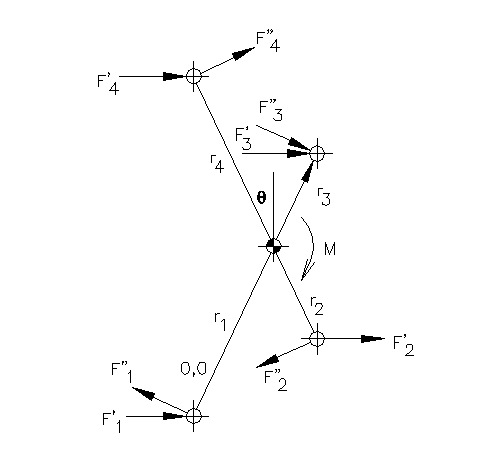
From the vector diagram, it is clear that bolt 4 takes the highest load. (From the structure of the moment equation, outermost bolts take more load.) The Fi' numbers are primary shears, assumed equally distributed.
A grade 8 bolt whose yield strength is 120 ksi would just be able to take this load. (Fsy = 60 ksi.) If the bolt is stainless with Fy=35 ksi, the bolt would have to be much larger.
The choices are: Grade 8 bolt, or 1" diameter stainless steel bolt.
CONCLUSIONS
Last modified 04/28/99
boroski@fnal.gov