PURPOSE OF TRIP:
Define the vertical and horizontal axes of rotation of the wind baffle
structure and the vertical axis of rotation of the rotator with respect
to the vertical and horizontal axes of rotation of the SDSS 2.5 meter telescope.
ITINERARY:
Bill Boroski, Charles Wilson, and I departed Chicago on June 9th, 1998,
arriving at APO the same day. We departed APO on June 13th, 1998, arriving
at Chicago the same day.
PERSONNEL CONTACTED:
Mr. Jon Davis, APO Telescope Engineer
Mr. Steven Bastian, on site mechanical support from Fermilab, PPD/TCD/MDM
Ms. Angela Prosapio, on site electronics support from Fermilab, PPD/TCD/EAP
ACTIVITIES AND RESULTS:
Orientation:
All values are in inches and all coordinates are defined and computed in the SDSS Building Coordinate System. That is, the horizontal axis of the telescope is defined as bearing due north when the Dog House is in its stow position to the west. For our computational purposes, the intersection of the vertical axis of the telescope with its horizontal axis is defined as X = 0.000, Y = 0.000, and elevation Z = 0.000. X is positive east, Y is positive north, and Z is positive up. The orientation of the system is building north. Where it is important, the location of the Dog House and the Rotator Arrow are provided. The Rotator Arrow is a name given to an arrow that was previously drawn on the rotator disk. The arrow was used as a point of reference. All axes of rotation referred to in this report are mechanical. All heights are relative to gravity, however, due to the instability of the level setups, no common datum could be maintained. All field notes have been scanned into this report as attachments. The original notes are recorded in Book 131-1 and archived at our office.
Day 1 Effort:
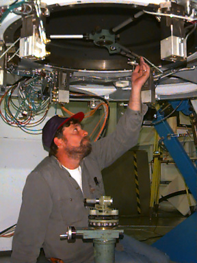
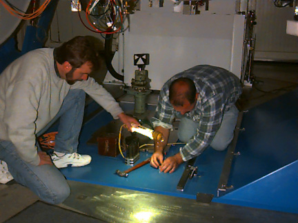
1) The vertical axis of rotation of the telescope was established using
standard techniques. With the telescope in its stow position, a random
center of rotation point was targeted with a two way adjustable target
that was placed on the instrument lift plate, as shown in Figure 1.
2) Measurements were then recorded to a 1/4-inch hole in the hydraulic lift plate used to mount telescope instruments onto the rotator. The center of the hole lies north 0.068" and west 0.010" from the vertical axis of rotation of the telescope.
3) To define the eccentricity of the vertical axis of rotation of the
wind baffle structure relative to the telescope vertical axis of rotation,
string lines (~0.044" width) were strung across the wind baffle frame using
the mounting bolt pattern for the wind baffle as a reference. The intersection
of these strings was the only available definition of the center of the
wind baffle assembly since the wind baffle itself was not on the telescope
when these measurements were made. Offset measurements to the string
line intersection were taken on day 3 by observation only, using the width
of the string line for perspective and scale. Therefore, the result is
only accurate to one string width or +/- 0.044 inches. This was deemed
acceptable, since the bolted connection of the wind baffle to the frame
allows some adjustment for clearance issues. These measurements were made
with a Zenith optical instrument, which projected the vertical axis of
rotation of the telescope up through the mirror housing's central hole.
It should be noted that this string line was monitored throughout the work
involving the installation of the cam followers and the radial alignment
of the wind baffle wheels for any unusual movement. No unusual movement
was detected.
4) To define the eccentricity of the vertical axis of rotation of the
Rotator relative to the vertical axis of the telescope, a Spider Mic was
installed on the inner radius of the Rotator. As seen in Figure 2, this
device is a three point 120 dig. adjustable radial arm instrument that
was oriented to the three kinematic mounts (120 dig. apart) located on
the Rotator. In the center of the Spider Mic is a target that was adjusted
onto the vertical axis of rotation of the Telescope for all measurements
using the Zenith optical instrument. Two measurements were made with the
Dog House to the east and the arrow on the rotator pointed to the Dog House
to check for repeatability. The Rotator was subsequently rotated 180 degrees,
with the Dog House still to the east and the arrow now pointed to the west.
The Spider Mic target was again brought onto the telescope vertical axis
and a third set of measurements were taken. The repeatability of these
measurements is +/- 0.002". Using the average of measurements #1 and #2,
then averaging that value with measurement #3 indicates that the center
of rotation of the Rotator lies north 0.070" and west 0.018" from the vertical
axis of rotation of the telescope. The Rotator mean center of rotation
w.r.t. the 1/4" hole on the hydraulic lift plate lies north 0.002" and
west 0.008".
5) To define the horizontal axis of the telescope, monofilament line was strung across the bolt pattern of the cover plates located radially in from both the north and south telescope altitude bearing assemblies. The line is 0.017 inches in width and forms a target (cross) at each end of the telescope where the lines intersect. These targets are visible when looking through the 1 inch bore of the wind baffle horizontal axis on each end. For verification that these targets actually identified the center of rotation of the horizontal axis of rotation of the telescope, see day 3 effort. The lines were left in place for future use if necessary.
Day 2 effort:
1) To identify any shimming that might be required during the cam follower installation and the radial alignment of the wind baffle wheels, it was necessary to define the magnitude of the difference between the horizontal plane of the wind baffle rotation about the vertical axis w.r.t. the telescope horizontal plane. The monofilament line targets strung the day before were used to define the horizontal axis of the telescope. The horizontal axis was rotated over each wind baffle wheel (Azimuth motors). At each of the three azimuth motors, differential heights were taken from the monofilament targets to the center of the 1 inch bore of the wind baffle bearing assembly and end to end. These measurements, summarized in Table 1, revealed that the wind baffle horizontal plane was not coplanar with the telescope horizontal plane.
|
|
|
|
||||
|
|
|
|
|
North
Fork
(in) |
South
Fork
(in) |
|
| Az motor #1 | 87.899 | 87.849 | 0.050 | 87.826 | 87.605 | 0.221 |
| Az motor #2 | 87.904 | 87.859 | 0.045 | 87.844 | 87.624 | 0.220 |
| Az motor #3 | 87.903 | 87.876 | 0.027 | 87.854 | 87.645 | 0.209 |
|
Mean:
|
87.902 | 87.861 | 0.041 | 87.841 | 87.625 | 0.216 |
The distance between the telescope altitude axis targets was 111.50". Give the average elevation change of 0.041" from the north to south fork, the telescope altitude axis is 0.021 degrees off of perpendicular with respect to the telescope azimuth axis, assuming the azimuth axis is perfectly vertical.
The distance between the wind baffle axis targets was 179". This
dimension was obtained from telescope drawings. Given the average
elevation change of 0.216", the wind baffle altitude axis was 0.069 degrees
off of perpendicular with respect to the azimuth axis.
2) To define the eccentricity of the telescope altitude rotation about the horizontal axis w.r.t. the monofilament lines, measurements were taken with the telescope at zenith and ~90 dig altitude. The readings were averaged and yielded a slope difference of ~0.180", the south end of the wind baffle being consistently low. Since the slope of the wind baffle altitude axis was always from the north to the south fork, and since the magnitude of the slope was constant within the accuracy of these measurements, the measurements indicated that the wind baffle azimuth motor elevations did not have to be shimmed. We noted that the wind baffle altitude bearings are located in pillow blocks that are bolted to the top of the wind baffle frame fork. By adding a shim under the pillow block on the south fork, we felt we could bring the wind baffle altitude axis plane parallel with the telescope altitude axis plane. With this information in hand, the installation of the cam followers and radial alignment of the wheels for the wind baffle azimuth rotation commenced. With the telescope locked out from movement, the alignment crew assisted in this installation.
Day 3 effort:
1) While the final installation of the cam followers was being done, the alignment crew perpetuated the mechanical centerline of rotation of the vertical axis of rotation of the telescope. K&E stick-on targets were placed on the blue yoke of the telescope using the scribe marks from day 1. Additionally, as seen in Figure 3, a punch was used to place permanent marks in the telescope fork along the scribe lines. The four K&E targets and punch marks in the steel are in the cardinal quadrants and their intersection defines the center. In all cases, the punch marks in the steel are ~3" radially out from the K&E targets. When the Dog House is in its stow position, the NE K&E is ~30" radially out from the center. The NE K&E is ~24" radially out, the SW K&E is ~24" radially out and the SW K&E is ~30" radially out from the center. In addition, a K&E target was set on the hydraulic lift plate over the 1/4" hole to define the mechanical center of rotation of the telescope. This target, being in the way, will probably not last.
2) To control the shimming of the south pillar of the wind baffle bearing assembly, and to check the monofilament lines strung to define the horizontal axis of rotation of the telescope, elevation and offset control lines were established.
With the telescope horizontal axis in an east/west position for crane coverage, Dog House to the south, using the altitude drive disc as a reference and holding the radius of the disc to the horizontal axis of rotation of the telescope to the machined tolerance of 50.015" +/-0.010 as per the specifications/drawing, a measurement was made to the monofilament line strung during day 1. The monofilament line measured +0.008" south from the ideal radius. This confirmed that the monofilament lines strung on day 1 defined the center of rotation of the horizontal axis of the telescope within our ability to measure it.
Before shimming, the wind baffle horizontal axis was set parallel, in azimuth, to within 0.030" of the telescope axis. This was accomplished by mechanically aligning the rectangular opening in the wind baffle floor with the telescope fork. At this point, Jon Davis pointed out a rotational misalignment between the wind baffle altitude pillow blocks and the wind baffle fork. The pillow block on the south fork was not properly aligned on its mounting pad; it was skewed by quite a bit. We decided to try to re-align the block during the shimming operation. During the subsequent shimming operations, friction of the wind baffle azimuth drives kept the wind baffle from moving in azimuth. The telescope was held stationary by applying the azimuth brake.
Levels were set up on each end of the telescope horizontal axis and measurements were taken before and after shimming. To insert the shim, the pillow block on the south wind baffle fork was loosened and the enclosure crane was used to lift the wind baffle frame slightly. A 0.190" shim was inserted between the pillow block and the wind baffle frame. The pillow block was mechanically aligned with the mounting pad, the wind baffle frame was lowered onto the fork, and the bolts re-tightened. The final result of the shimming yielded end-to-end elevation differences below 0.005". The horizontal plane of the wind baffle is now vertically coplanar with the telescope horizontal plane to within +/- 0.010", which is the accuracy of these measurements. Table 2 summarizes the end-to-end elevation measurements before and after shimming.
|
|
|
|
||||
|
|
|
|
North
Fork
(in) |
South
Fork
(in) |
|
|
| Before shimming | 107.111 | 107.093 | 0.018 | 107.120 | 106.903 | 0.217 |
| After shimming | 107.111 | 107.087 | 0.024 | 107.112 | 107.090 | 0.022 |
Once the shimming operation was complete, the wind baffle horizontal axis was checked again for horizontal parallelism with the telescope axis. The final measurements revealed that the wind baffle horizontal axis is not coaxial to the telescope horizontal axis by 0.020" counterclockwise.
Since the telescope and wind baffle horizontal axes were reasonably well aligned in azimuth, the telescope alignment clamp was re-adjusted to maintain the proper rotational alignment between the telescope and wind baffle. Before the telescope azimuth brake was released, the female portion of the alignment clamp (that piece affixed to the telescope fork) was loosened and the clamp actuated several times. The actuating action caused the female portion to center itself on the clamp actuator arm. Once the female part had found its center, the bolts were tightened to fasten the part to the telescope fork. The part is now ready to be pinned in place.
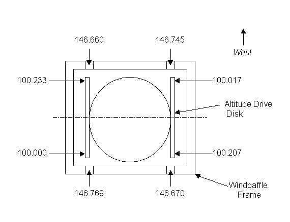
3) After shimming was complete, elevation measurements were made at each of the wind baffle mounting surfaces to determine the flatness of the wind baffle frame. As a point of reference, elevation measurements were also made on the flat edge of the telescope altitude drive disks, i.e., the flat side of the semi-circular disks. All measurements were made with the telescope pointed at zenith. The results of these measurements are shown in Figure 4.
4) The final measurement effort involved observing the offsets of the
string line that was installed on day 1 across the top of the wind
baffle frame w.r.t. the mechanical center of rotation of the vertical axis
of the telescope. With the telescope in its stow position, the intersection
of the string lines (by estimation only) lies north 0.022" and west 0.066".
Rotating the telescope 180 degrees, the string line lies south 0.044" and
east 0.088" from the vertical axis of rotation of the telescope.
Averaging these values defines the center of rotation of the wind baffle
w.r.t. the telescope vertical axis of rotation. This point lies south 0.011"
and east 0.022" with an accuracy of +/- 0.044".
CONCLUSIONS AND RECOMMENDATIONS:
With the exception of the 0.190" shim applied to the south bearing cap of the wind baffle and the apparent Rotator offset of 0.072" to the north and west of the mechanical rotation of the vertical axis of the telescope, the overall alignment integrity of the telescope and wind baffle structure appears to be in good shape.
The amount of work involved for this project was too great for the 2.5 days allotted for it. As it was, we extended the trip to 3 full days to complete the task. However, there was no time for any quality control or final checks of the shimming for various rotations about the vertical axis. I would recommend that this be done at some point. I would also recommend that alignment be incorporated into the design and construction of any future telescopes in order to avoid having to accept less than optimum targeting and accessibility.
I would like to thank Angela Prosapio, Steve Bastian, and Jon Davis for their long hours of effort and assistance to complete this task. I would also like to thank the alignment crew chief Chuck Wilson for his long hours of dedicated measurements and George Wojcik for his quality control checks of the computations.