The objectives of this trip to APO were to:
INTRODUCTION
The team working on these tasks included Steve Bastian, Jon Davis, Angela Prosapio, Terry Sager, Chuck Wilson, and Bill Boroski. Terry Sager is the head of the Alignment Group at Fermilab. Chuck Wilson is a member of this group.
Tuesday was primarily a travel day. Chuck, Terry, and Bill arrived at APO in the late afternoon and spent the remainder of Tuesday getting settled in and getting Chuck and Terry acquainted with the telescope and wind baffle assemblies. Angie had a later flight into El Paso, so she arrived at the site on Wednesday morning.
As the wind baffle and secondary truss were removed from the telescope,
we were able to do all of our work inside the enclosure. This was beneficial
since it rained throughout our visit. It should be noted that all
measurements in this document refer to mechanical axis positions. No efforts
were made to correlate the mechanical axis positions with optical axis
positions.
INITIAL ALTITUDE AXIS MEASUREMENTS
Our plan was to re-align the wind baffle azimuth drive motors at the same time that we installed the cam followers. Aligning the drive motors included radial re-positioning to align the drive wheel axis with the center of rotation of the wind baffle rotating platform, and vertical re-positioning to make the wind baffle altitude axis coaxial with the telescope altitude axis. We used an alignment fixture to accomplish the radial alignment. To determine the amount of vertical shimming required, we used surveying techniques to determine the plane of the wind baffle altitude axis with respect to the plane of the telescope axis.
In order to establish the position of the telescope altitude axis, we needed a target at the center of the rotating portion of the altitude bearing. After reviewing various telescope drawings, we determined that the only way to access this was from the inside of the primary mirror cell. Jon, Angie, and Bill carefully removed all of the plywood mirror covers and those sections of the primary mirror retaining ring and perimeter seal near both altitude bearings. Terry was then able to reach into the altitude bearing and string monofilament fishing line around the bolts to form an X near the center of each bearing. By aligning survey scopes at each end of the altitude axis, one could look through the bore of the wind baffle altitude axis and watch the movement of the fishing line cross-hair as the telescope was rotated. We noted that the crosshairs moved off-axis by 0.008". Since our measurement accuracy was +/- 0.010", we defined the string crosshairs as the centers of the telescope altitude bearings. We did not remove these strings after completing our alignment work. They were left in place for possible future use.
It was much easier to establish the center point of the windbaffle altitude bearings. The bore through the windbaffle bearings has an inside diameter of 1 inch. Chuck had brought along 1" o.d. bushings that accepted survey targets at their centers. Thus, all we had to do was insert a bushing into the wind baffle bore, then insert the survey target into the bushing. With these targets in place, we again rotated the telescope/windbaffle assembly in altitude and watched the change in position of the survey targets. As with the telescope axis, the movement of each target was within the accuracy of our measurements and so we defined these targets as the center of the wind baffle altitude axis at each fork.
We subsequently proceeded to measure the plane of both the telescope
and wind baffle altitude axes with respect to gravity by measuring the
elevation of the center targets over each of the wind baffle azimuth drive
motors. We used the wind baffle manual control box to move the wind baffle
in azimuth until the altitude axis was positioned over one of the windbaffle
azimuth drive motors. We then manually centered the telescope within the
wind baffle by pushing on the telescope fork. The elevation of the telescope
and wind baffle altitude bearings was measured and then the assembly rotated
to the next drive motor. This sequence was repeated for each of the drive
motors. Table 1 shows the results of the initial elevation measurements.
|
|
|
|||||
|
|
|
|
|
|
|
|
| Az Motor 1 |
|
|
|
|
|
|
| Az Motor 2 |
|
|
|
|
|
|
| Az Motor 3 |
|
|
|
|
|
|
|
Mean
|
|
|
|
|
|
|
The distance between the telescope altitude axis targets was 111.5". Given the average elevation change of 0.041" from the north to south fork, the telescope altitude axis is 0.021 degrees off of perpendicular with respect to the azimuth axis.
The distance between the wind baffle axis targets was 179". This dimension was obtained from telescope drawings. Given the average elevation change of 0.216", the wind baffle altitude axis was 0.069 degrees off of perpendicular with respect to the azimuth axis.
Since the slope of the wind baffle altitude axis was always from the north to the south fork, and since the magnitude of the slope at each motor location was constant within the accuracy of our measurements, the measurements indicated that the wind baffle azimuth motors did not have to be shimmed in elevation. We noted that the wind baffle altitude bearings are located in pillow blocks that are bolted to the top of the wind baffle fork. By shimming under the block on the south fork, we felt we would be able to bring the wind baffle altitude axis parallel to the telescope altitude axis. We decided to do this after we installed the wind baffle azimuth guide rollers and re-aligned the azimuth drive motors.
MOTOR ALIGNMENT AND WIND BAFFLE GUIDE ROLLER INSTALLATION
During the process of installing the guide rollers, we also moved the drive wheel flanges away from the drive disk and realigned the azimuth drive motors radially and horizontally. We worked on one motor assembly at a time. We started by placing dial indicators on the bottom of the drive disk to verify that the adjustments did not change the wind baffle floor elevation. We used two dial indicators for this purpose. We placed the indicators approximately four feet away on either side of the drive motor. With the indicators zeroed, we used a hydraulic ram to lift the wind baffle platform off of the drive roller. The ram was placed between the concrete pier and an appropriate box beam on the floor structure. We tried to get as near to the motor as possible, and only lifted the floor assembly high enough to see light between the drive roller and drive surface. We subsequently loosened the four mounting bolts that held the motor in place and adjusted the radial alignment bolts to move the motor towards the telescope center until we had a gap of approximately 0.375" between the roller flange and drive disk. We then installed the alignment bracket designed to align the motor radially with respect to the drive disk inner radius. The alignment bracket was also designed to set the final spacing between the roller flange and drive disk at 0.375 inches.
With the alignment bracket in place, we slowly adjusted the radial alignment bolts on the motor housing until the tooling balls on the alignment bracket contacted the inner radius of the drive disk. At this point, we tightened the mounting bolts and snugged all four radial alignment bolts, then rechecked the tooling balls to make sure we were still in proper contact with the drive ring.
We then slowly lowered the rotating platform back onto the drive wheel, checking the dial indicators to make sure elevation hadn't changed. For all three motors, the largest elevation shift seen was 0.003". We also sighted along the bottom of the drive disk across the drive roller to make sure the drive disk was sitting flat on the roller. On Az Motor 1 and Az Motor 2, no light was seen passing between roller and disk. On Az Motor 3, there was slightly more light passing between the roller and the drive disk near the flanged side of the roller. We used shim stock to check the height of the gap, which we determined to be <0.001". With such a small gap, we did not change the angle of the motor mount.
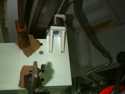
Once the motor assembly was properly aligned and bolted in place, we raised a guide roller assembly into position and clamped the assembly to the drive motor, as shown in Figure 1.
We used a 0.010" thick piece of shim stock to set the spacing between the guide roller wheel and the drive disk inner radius, and adjusted the angle of the roller assembly to make sure we had full contact between the roller and disk. With the assembly properly positioned, we transfer-punched the mounting hole locations onto the drive motor housing. The guide roller assembly was removed from the motor housing and the mounting holes drilled and tapped.
The first guide roller assembly, mounted onto Az Motor 3, was installed
with no problem. We ran into clearance problems when we tried to install
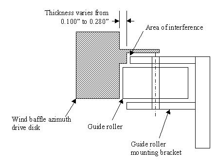
the roller assemblies onto motors 1 and 2. As shown in Figure 2, there
is a step above the machined drive surface that was left behind after the
drive disk radius was machined. The top of the roller assembly bracket
was hitting this step at motor locations 1 and 2. Angie measured the width
of this step around the drive disk and found that the width varied from
0.100" to 280". One of the thinner spots just happened to be near Az Motor
3, which is why it went on with no problem .
To provide adequate clearance between the guide roller brackets and the drive ring, we modified all three bracket assemblies by removing 0.300" of stock from the bracket area adjacent to the interference. Once modified, all three guide roller assemblies were installed without further difficulty. Many thanks to Steve Bastian and Jon Davis for making these modifications quickly.
As the roller assemblies were being installed, Steve also filed away a large burr that had developed on the inner edge of the drive disk due to previous contact with the drive wheel flanges. We were concerned that this burr would cause premature wear on the guide roller surfaces and wanted to remove it before rotating the wind baffle across the guide rollers.
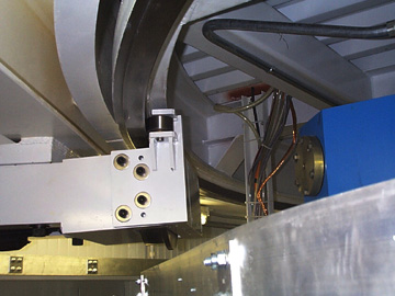
After all three assemblies were installed as shown in Figure 3, we tested the operation of the guide rollers by rotating the telescope assembly in azimuth. Because we were still working inside of the enclosure, we were only able to rotate approximately 210 degrees. Chuck, Steve, and Bill each positioned themselves near one of the motor assemblies, while Angie drove the wind baffle using the manual control box. We noted that the rollers turned with no effort when in contact with the drive disk. We also noted that the disk assembly was usually in contact with two of the three rollers, but not always in contact with the same two. This suggested that the assembly was not always trying to drive itself off axis in the same direction. We also noted a couple of occasions in which the gap between the drive disk and one of the drive rollers would become quite large. We measured these gaps; the largest gap was 0.048" and occurred between the # 2 motor roller and drive disk when the dog house was over that motor location. While we were rotating, we also watched the alignment of the drive and guide rollers with respect to the drive disk surfaces. We noted that the drive disk surfaces are not flat and perpendicular. The angle of contact between the rollers and drive disk would vary slightly as the assembly was rotated. There were no trends or tendencies, nor were the gaps ever very large. We measured the largest gap we saw; it turned out to be <0.0015".
With the installation and testing of the guide rollers and motor alignment complete, we proceeded upstairs to re-check the alignment and shim the windbaffle assembly.
WIND BAFFLE SHIMMING
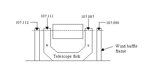
We positioned the telescope assembly so that the altitude axis was oriented east and west, with the dog house to the south, and re-measured the elevation of the telescope and wind baffle altitude axes. This orientation positioned both wind baffle pillow blocks under the overhead crane in the telescope enclosure. The initial measurements are shown in Figure 4.
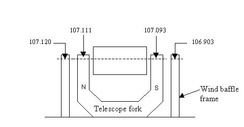
From these measurements, the slope of the telescope altitude axis is 1.61 x 10⁻⁴ in/in. Extrapolating this slope to the position of the wind baffle targets, the elevation at the north target should be 107.125 and the elevation of the south target should be 107.088. Since the north elevation was off by 0.005", no adjustment was needed. However, since the south elevation was low by 0.185", we decided to add a shim between the wind baffle fork and altitude bearing housing to raise the bearing center to the proper elevation.
We loosened the bolts securing the wind baffle assembly to the support fork and used the overhead crane to lift the south end of the wind baffle frame assembly. While the bolts were loose, we shifted the pillow blocks so the bolt washers fit properly into their respective counterbored holes. We slipped a shim pack, which actually measured 0.190", between the fork and bearing housing and lowered the frame. We also measured the radial alignment between the wind baffle and telescope and adjusted the wind baffle frame horizontally until the two axes were aligned to within .030" from end to end. After tightening down the wind baffle pillow blocks, we sighted on the wind baffle targets and re-measured elevation. Final elevation measurements are shown in Figure 5.
Guide rollers have been installed on the wind baffle azimuth motor housings to keep the rotating floor centered on its axis. The rollers are positioned to keep the drive disk at least 0.375" away from the flanges on the azimuth drive wheels. The guide rollers are bolted in place but not pinned. Once the telescope assembly has been exercised in azimuth and the roller mount locations determined to be adequate, the mounting brackets should be pinned to the motor housings to maintain their position.
Last modified 08/05/98
boroski@fnal.gov