The field operation of the Instrument Latches built by Fermilab for the Sloan Telescope has been reasonably successful so far. The design of the latches incorporates two different mechanisms in its power and return strokes. The latch uses a pneumatic cylinder to push the latch hook out to engage with instruments on the rotator of the telescope, and it uses a spring to retract the latch hook when an instrument is to be dismounted from the telescope. Unlatching is signalled when the latch hook retracts far enough into the housing to actuate a microswitch.
In October of 1998, Corrector Latch #1 was returned to FNAL with a bent retraction spring. This failure was a type that was never seen in thousands of test cycles in the lab. The bending of the retraction spring made it about one and a half coils longer than its normal free length, which prevented the latch hook from retracting all the way and signalling that it was unlatched. The latch hook was only protruding from the latch by less than an eigth of an inch, so the camera could be removed from the telescope, but it was decided that this failure mode was serious enough to need immediate correction and prevention. The latches are intended to be 100% reliable and to avoid jeopardizing the camera in any way.
Upon examination, we saw that there was freedom for the retraction spring to move from side to side inside the latch along the roll pins that fasten the spring to the housing and back side of the latch hook. Each end of the spring was free to move independently of the other so that the axis of the spring could become tilted out of the plane of the hook's motion. If the spring becomes too far tilted from the hook's swing plane it could be crushed between the retracting latch hook and the inside of the housing. This is apparently what happened to Corrector Latch #1. Because no solution was available on the short time scale that the latch was needed back on the telescope, it was decided to fix Corrector Latch #1 with a new spring, return it, and then design a fix for all of the latches that could be implemented at the next down time. The next time the latches became available was early December 1998.
Several options for modifying the latches were considered. The one that was accepted was the idea of adding sleeves on the roll pins to either side of the hooks on the ends of the spring so that the spring could not move significantly sideways in the openings of the housing or latch hook. This idea involved the minimum number of changes to the original latches and parts could be fabricated in advance of the return of all of the latches. Sleeves were fabricated in the Fermi shop and installed in early January. The latches were all tested successfully on the test fixture at Fermilab and returned to APO on 1/20/99. Latches were tested at room temperature to just over 200 cycles each. Details of the tests and all adjustments made are available in the latch log book at Fermilab.
These images were taken by Larry Bartoszek at the Industrial Center Building Engineering Lab at Fermilab.
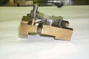 Half of a latch showing sleeves, 34K
This photo shows a latch disassembled. The pneumatic power unit and half of the housing is not shown to expose the latch hook and the retraction spring. The roll pin in the latch housing has the two bronze sleeves on it which prevent the retraction spring from moving from side to side.
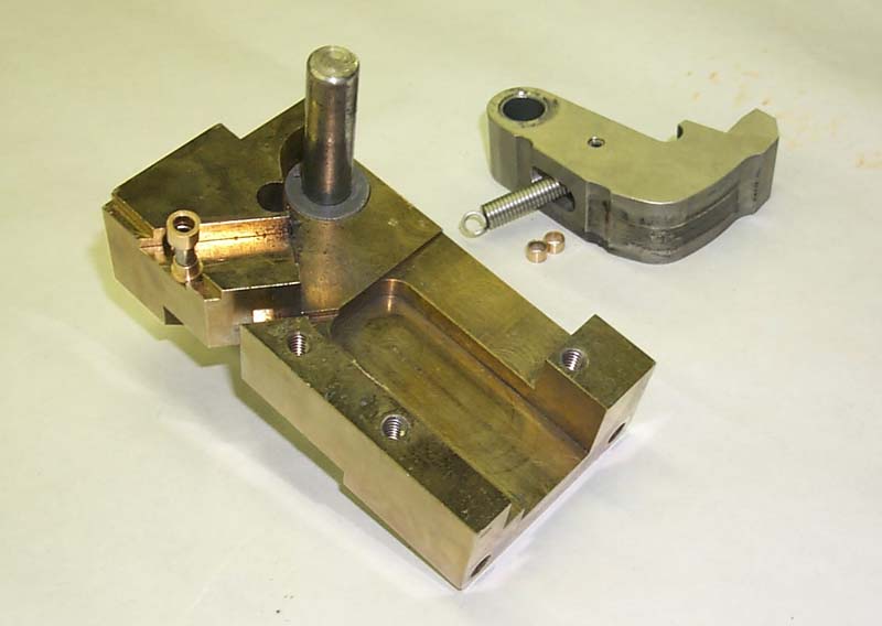
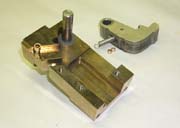 Latch "exploded" view, 33K
In this picture the latch hook has been removed from the shaft it rotates on and the sleeves have been placed near their components. There are three different sleeve designs. Sleeves inside the latch hook must have a smaller outer diameter than housing sleeves because the slot cut into the back of the latch has a rounded bottom which comes fairly close to the roll pin hole. The housing sleeves are different because the spring hooks are asymmetrical. The last coil of the spring on both ends bends in a gentle curve to form the base of the spring hook. This curve iterferes with a larger diameter sleeve, so the sleeve on that side of the spring is cut down in diameter to fit within the curve.
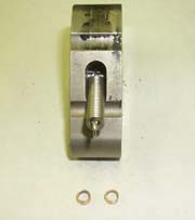 Hook with sleeves, 21K
This picture shows the inside of the slot in the back of the latch hook and clearly shows the asymmetry of the spring hooks. Getting the sleeves onto the roll pins is accomplished with two roll pin drift pins. One is used with an arbor press to move the roll pin out of the hook just past the mid plane of the slot, creating enough room to bring in the sleeves and the spring. The first sleeve is assembled onto the stub of the roll pin inside the latch hook slot. The other roll pin drift is pushed through the opposite side of the hook and is used to support the second sleeve before the final roll pin is pushed through. There must be enough space between the two sleeves in the hook slot to allow the spring to be inserted. After the spring hook passes between the sleeves the second drift pin is pushed all the way in until it touches the roll pin. This traps the spring onto a continuous shaft. The final step is to push the roll pin into the hook while allowing the second drift pin to back out.
Questions regarding this note should be addressed to Larry Bartoszek by phone at (630) 844-9369 or by e-mail at
bartoszek@fnal.gov.
Last modified 03/09/99
boroski@fnal.gov
 Half of a latch showing sleeves, 34K
 Latch "exploded" view, 33K
 Hook with sleeves, 21K